
|
Most multimedia applications make extensive use of video, audio, and images. As the storage space needed by such multimedia material increases, compression techniques are becoming an indispensable tool for these applications. This paper explains the basic principles of an image compression technique known as vector quantisation (VQ). The reasons why image compression is quickly becoming an indispensable tool in applications such as image databases and other multimedia packages are examined. The differences between scalar and vector quantisation are also explained. The basic operations of a vector quantiser are described and its advantages and disadvantages discussed. A brief update on current VQ research is given, showing how some of the VQ disadvantages can be minimised, and a comparison is made between a number of advanced image compression techniques, showing how VQ can be effectively integrated with other methods.
Vector quantisation can be considered to be a pattern matching process in which image blocks to be coded are matched with predefined blocks. The compression arises from the need to use less information to specify the predefined blocks. This paper is a tutorial presentation on vector quantisation. After introducing VQ, this paper will then delve into some more advanced VQ techniques. The following topics will be explored:
The figure below shows an 8 x 8 grey scale image on the left and its equivalent digital representation on this right. Each number represents the intensity value of the corresponding pixel. The image representation is to be compressed by quantising its pixel values. Note that in reality, scalar quantisation is rarely done on an unprocessed image. In a compression method known as the differential pulse code modulation (DPCM) scheme (Gersho & Gray, 1992) for example, the pixel difference is coded. Here, however, the objective is to explain scalar quantisation.
Figure 1: A sample block of image pixels with its equivalent
numerical representation on the right
We assume that the image is to be compressed so that each pixel can be represented by just 2 bits instead of 8 bits. A quantiser can be described by its decision and reconstruction levels. For a variable X to be quantised, the quantisation rule operates as follows: if X falls in the decision region defined by xi and xi + 1 then it is mapped to or quantised to the corresponding reconstruction level yi. The layout of such a quantiser is shown below:
Figure 2: A scalar quantiser
There are basically two types of scalar quantisers: uniform and non-uniform (Netravali & Haskell, 1989). The non-uniform quantiser can be optimised by using the Lloyd-Max quantiser algorithm (Netravali & Haskell, 1989). This quantiser has decision and reconstruction levels that yield the minimum distortion level for a given bit rate.
| i | Decision level xi | Reconstruction level yi | Reconstruction level index |
| 0 | 0 | 0 | 00 |
| 1 | 55 | 111 | 01 |
| 2 | 146 | 181 | 10 |
| 3 | 206 | 231 | 11 |
| 4 | 255 | - | - |
With the example of coding the 8 x 8 image, a sub-optimal scalar quantiser described by the table below is used. The reconstruction levels are also assigned binary codes so that the effective amount of bits transmitted by the encoder is 2 bits per pixel (bpp).
For example, coding the first row of the image will yield the following output values: 111, 111, 231, 231, 181, 181, 231, and 0. These correspond to the following bit values: 01, 01, 11, 11, 10, 10, 11, and 00. A graph showing the decision and reconstruction levels along with a scatter plot of the grey value probabilities is displayed below.
Figure 3: Graph of a scalar quantiser's important data
The fidelity of the quantiser can be gauged by finding the mean square error (MSE) of the reconstruction. MSE is defined as:
A smaller MSE value indicates a higher reconstruction fidelity. In this example, the total number of pixels N is equal to 64. The MSE can be calculated to be 9583. A more popular measure of reconstruction fidelity is the power signal to noise ratio (PSNR). For a 256 level grey scale image, PSNR is defined as:
A larger PSNR value indicates a higher reconstruction fidelity. For our example, PSNR is equal to 26.4 dB.
In vector quantisation, instead of coding individual values, a block of values, or a vector, is considered. For our example, we will take a block size of 2 x 2 pixels. The first step in VQ is to construct a codebook. This codebook consists of a set of different 2 x 2 pixel blocks or codewords, Xi', i = 1,..., Nc, where Nc is the number of codewords. The bit rate of the coder depends on the number of codewords in the codebook.
For example, if there are 8 codewords in the codebook, the bit rate is:
After the codebook has been created, the encoding of the image begins. The operation is shown on the figure below. First, the image is divided into blocks of 2 x 2 pixels. Next, each image block X is compared to each of the entries Xi' in the codebook. The codeword that results in the least distortion is chosen and its index k is transmitted to the channel.
log2 (number of codewords)
block size= log2 8 bits
4 pixels= 0.75 bit per pixel
At the receiver, for each index k that is received, a table look up operation is performed. The codeword corresponding to k is retrieved from the codebook and is transmitted to be reconstructed. The reconstructed image is fully formed when all the indices have been received.
As before the fidelity of this codec (coder/decoder) can be evaluated by finding the PSNR. For illustrative purposes, an optimal codebook specific to the image to be coded will be used here. In practice it is virtually impossible to get such a codebook. The reason will become clear when codebook construction is explained later. The codebook is shown on the figure below. In examining the original 8 x 8 image, one can see that it has 9 different types of 2 x 2 blocks. Since our codebook will have only 8 codewords, codeword 111 is assigned to the combination between the last two 2 x 2 blocks shown on the figure below. Thus, we can expect fairly high reconstruction quality since only 2 blocks out of 64 are different from their original. The PSNR can be calculated to be 27.6 dB.
Figure 4: Block diagram of a vector quantiser
Using scalar quantisation, 2 bpp are needed to yield a PSNR of 26.4 dB. VQ is more efficient, yielding 27.6 dB with only 0.75 bpp. It should be noted that this simple example only serves to illustrate that it is more efficient, in the sense of reducing data rate, to code vectors instead of scalars. The actual use of VQ is much more complicated and not as efficient as shown here.
Figure 5: Codebook
The key to high image reconstruction quality is to have a codebook that matches the average image to be coded well. For this reason, codebook construction is a very important component of VQ.
Codebook design commonly requires a set of training images since accurate image statistics are usually unobtainable. Factors to be considered are the number of training images, the number of codewords in the codebook, and the dimension of the vector. Each of these represent a trade off between a pair of these parameters: image quality, bit rate, compression time, and memory requirements.
The construction of an initial codebook is an important procedure because a good initial codebook will help ensure that an efficient resulting codebook will be produced after the generalised Lloyd algorithm (Gersho & Gray, 1992) of the next step. There are a number of ways to construct an initial codebook (Netravali, 1989) (Gray et al., 1992) (Gersho & Gray, 1992):
The practical solution is as follows: a reasonable amount of training images is first used to create the codebook. The robustness of the codebook is tested by using it to code a number of images that were not in the training set. If the results produced are satisfactory (the distortions produced are close to the average distortion value that was used for creating the codebook), it suggests that the number of training images used is sufficient.
2. Codebook improvement: the generalised Lloyd algorithm
Once an initial codebook has been constructed, the next step is to run an iterative codebook improvement algorithm to optimise it. A vector quantiser can be considered optimal if it minimises the average distortion for the given parameters of dimension, codebook size, and number of training images. The most common codebook improvement algorithm is the generalised Lloyd (GL) algorithm, which is commonly but less appropriately referred to as the LBG (Linde Buzo Gray) algorithm. With a given initial codebook Xi', i = 1,2,..., Nc, a distortion measure d(X, X'), and average distortion D, the algorithm proceeds as follows:
An important point to note is that the GL algorithm can only be optimum for the initial codebook the algorithm started with. In other words, only a local optimum can be obtained. Other codebook improvement techniques aim to provide a more global optimum by introducing randomness in the codebook shaping process so that there is less dependency on the initial codebook. A family of such algorithms in based on a method called stochastic relaxation (Gersho & Gray, 1992).
The encoding operations can be very lengthy, depending on the vector dimension and the size of the codebook. The search technique is known as exhaustive searching since every codeword is compared to the image vector. For the MSE distortion criterion, each comparison can be mathematically described as:
where d(X, X') is the distortion measure and m is the vector dimension. For example, if the image vector to be coded, xi, is [3 1] and the codeword being compared to is [1.5 2],
The nearest neighbour codeword for an image vector is found when its d(X, X') value is lower than any other codeword in the codebook.
| R = | log2 Nc n | bits / pixel |
1. More effective codebook generation
The generalised Lloyd algorithm is improved with methods such as stochastic relaxation (codebook design is offline and an improvement of 0.5 dB in SNR can be effected) and fuzzy clustering. The codebook produced by such techniques are less dependent on the initial codebook when compared to the conventional method.
2. Faster encoding algorithm
This is accomplished in several ways. In tree structured VQ and lattice VQ, a structural constraint is imposed on the codebook. Such methods yield below optimal results but the reductions in complexity and encoding time can be enormous. Research has also been done to apply different search strategies. For example, the partial distance encoder progressively calculates the distortion value so that it can eliminate a large proportion of the codewords prematurely.
3. Generating more efficient codebooks
As mentioned earlier, an efficient codebook reflects accurately the properties of the images to be coded. One of the grave shortcomings with basic VQ is that the lack of constraints makes it very difficult to represent an "average* image successfully. Enhanced VQ try to more accurately pinpoint commonly used codewords by imposing constraints on the image structure. When the vector blocks to be coded have a smaller variance, it is also possible to reduce the size of the codebook.
One example is classified VQ, whereby a simple scheme is used to classify image vectors into edges and uniform blocks. A codebook is used for the edge codewords and a different one for the uniform block codewords.
Another example is the hybrid method that performs a discrete cosine transform (DCT) on the image block before vector quantising it. The DCT decorrelates the image block and helps to build a more focussed VQ codebook.
4. Higher compression rates
This objective is also related to higher efficiency codebook construction. Some methods used in current research include variable block sizes, larger vector dimensions, and smaller codebooks. Variable block sizes permit variable bit rates. A side benefit is that it enables the perceived quality to be approximately constant across the entire image. Also, this is beneficial with the advent of packet switching networks (eg. Broadband ISDN), whereby the data rate is not constant because data are only sent when necessary. Another efficient technique is entropy constrained VQ, in which the entropy cost of the codeword is included into the cost function, instead of just the MSE.
5. Adaptive VQ
A VQ system is adaptive if its codebook or encoding rule changes to match observed local statistics of the input sequence. Examples are mean adaptive VQ, switched codebook adaptation, variable bit rate VQ, and adaptive codebook VQ.
6. Reduction of the blocking artefact
This can be accomplished in a number of ways. One of the most effective is to use side match classified VQ (Kim, 1992). The encoder selects a codebook, from a number of different ones, according to the nearest row and column of the neighbouring blocks.
7. Progressive image transmission
Progressive image transform (PIT), also mentioned in the section "Why is image compression needed?", is a very powerful bandwidth reduction technique. Reduction is accomplished in two ways: compression of data and premature termination of transmission. The two dominant techniques in VQ are multistage VQ, where the residual error is coded each stage, and pyramidal VQ, where the image is coded hierarchically.
For the comparison here, the target images to be encoded are natural images, as opposed to computer produced graphics. The criteria chosen here are the very general ones: objective image quality and bit rate. The compression is made on how well a method can compress the Lena image. Lena is a 512 x 512 pixel 256 grey scale image that has become a very popular choice for simulations. The original image is shown below.
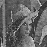
Figure 6: The Lena image used for comparison
The issue of subjective image quality is a very difficult one to solve in image processing. The most common measures of fidelity so far have been based on error norms such as the mean squared error (MSE). However, there is a human in the image compression loop, and the human observer is the final judge of the reconstructed image's fidelity. The problem with using criteria such as MSE is that such measures do not accurately reflect the perceptual notions of visual fidelity. An example of this observation can be seen by adding noise to an image.
If the noise is added randomly, the degradation will not be as noticeable compared to the degradation when the same amount noise is concentrated on a mall area of the image. Some suggested ways to overcome this problem is to introduce a weighting system into the distortion measure and to consider the modulation transfer function (MTF) of the human visual system. Two weaknesses with such solutions are that there is no commonly agreed method and there is a high computational cost. In addition, subjective quality often varies depending on the image compression's application. The current favoured solution is to publish a compressed image along with an original one. This is not done here due to the lack of space. However, they can be seen by looking up the appropriate journals referenced in this paper.
Most of compression methods analysed here involve some form of VQ but the fractal, wavelet, and JPEG compression methods do not. They are included on the basis that they are very popular in image compression research or yield very high compression ratios. The techniques listed here can be considered to be representative of state of the art methods in image compression. A more rigorous representation is very difficult to obtain since researchers do not publish their PSNR results and some do not simulate on the Lena image.
| Method | Bit rate (bpp) | PSNR (dB) |
| Darragh | 0.26 | 31.27 |
| Jacquin | 0.68 | 27.7 |
| Riskin 1 | 0.32 | 29.29 |
| Riskin 2 | 0.32 | 30.92 |
| Antonini 1 | 0.37 | 30.85 |
| Antonini 2 | 0.21 | 29.11 |
| Huang | 0.2 0.25 0.3 0.4 0.5 0.75 | 29.703 30.925 31.84 33.047 33.985 35.369 |
| Fisher | 0.2175 | 30.71 |
| Kim | 0.639 0.409 0.31 0.481 | 37.23 35.28 34.04 35.98 |
| Senoo | 0.136 | 30.91 |
| Andrew | 0.8 0.4 0.2 | 36 33 30 |
| Gharavi | 0.55 | 33.95 |
| Ngan | 0.45 | 34.25 |
| JPEG | 0.25 0.5 |
30.81 34.69 |
Figure 7: Graph showing comparison between various compression techniques
From table 2 and the graph on figure 7, it can be seen that full search VQ performs poorly. This confirms the observation made earlier that basic VQ is not an efficient compression method. However, when VQ is combined with other compression methods, the performance increase is significant. Outstanding methods are Kim and Modestino's and Senoo and Girod's compression schemes. However, one drawback with these methods is that the complexities and encoding times are usually quite imposing.
It can also be observed that the JPEG compression method performs very favourably. Another strong motivation to use JPEG is that it is a popular image compression standard and can be implemented rather easily. There are already many companies producing hardware for performing JPEG compression. However, JPEG is fast reaching its limitations, whereas it is still possible to improve on VQ based techniques.
VQ is currently a highly active area of research, arguably the most busy for image compression. The reason behind this is that there is still much room for improvement and new VQ based techniques have been shown to be able to outstrip other compression techniques significantly.
Antonini, M., Barlaud, M., Mathieu, P. & Daubechies, I. (1992). Image coding using wavelet transform. IEEE Trans. Image Proc., 1(2), 205-20.
Darragh, J. & Baker, R. (1988). Fixed distortion, variable rate sub-band coding of images. Proc. SPIE, 1001, 979- 990.
Fisher, Y., Jacobs, E. W. & Boss, R. D. (1992). In Image and Text Compression (ed J. A. Storer), Fractal image compression using iterated transforms. pp. 35-61.
Gersho, A. & Gray, R. M. (1992). Vector quantisation and signal compression, 1st edition. Kluwer Academic Publishers.
Gharavi, H. & Tabatabai, A. (1988). Sub-band coding of monochrome and color images. IEEE Trans. Circuits Syst., 35, 307-14.
Gray, R. M. (1984). Vector quantisation. IEEE ASSP Magazine, 1, 4-29.
Gray, R. M., Cosman, P. C. & Riskin, E. A. (1992). In Image and Text Compression (ed J. A. Storer), Image compression and tree-structured vector quantisation, pp. 3-34.
Huang, Y., Dreizen, H. M. & Galatsanos, N. P. (1992). Prioritised DCT for compression and progressive transmission of images. IEEE Trans. Image Proc., 1(4), 477-87.
Kim, T. (1992). Side match and overlap match vector quantizers for images. IEEE Trans. Image Proc., 1(2), 170-85.
Kim, Y. H. & Modestino, J. W. (1992). Adaptive entropy coded sub-band coding of images. IEEE Trans. Image Proc., 1(1), 31-48.
Netravali, X& Haskell, B. (1989). Digital pictures: Representation and compression, 1st edition. Plenum Press.
Ngan, K. N., Koh, H. C. & Wong, W. C. (1991). Hybrid image coding scheme incorporating human visual system characteristics. Optical Engineering, 30(7), 940-6.
Rabbani, M. & Jones, P. W. (1991). Digital image compression techniques, 1st edition, chap. 12. SPIE.
Senoo, T. & Girod, B. (1992). Vector quantisation for entropy coding of image sub-bands. IEEE Trans. Image Proc., 1(4), 526- 32.
Wallace, G. K. (1991). The JPEG still picture compression standard. Commun. ACM, 34(4), 3 144.
White, R. (1992). High performance compression of astronomical images. Internal report, University of Colorado.
| Authors: Mr. Y.-Kheong Chee, PhD Student, Curtin University of Technology, GPO Box U 1987, Perth WA 6001. Tel: (home) 313 1352 Email: scheeyk@cc.curtin.edu.au
Dr. T. Harry Edgar, Senior Lecturer, School of Electrical and Computer Systems Engineering, Curtin University of Technology, GPO Box U 1987, Perth WA 6001. Tel: 470 2428 Email: tedgarth@cc.curtin.edu.au Dr. Doug G. Myers, Head of Department, Computer Systems Engineering, Curtin University of Technology, GPO Box U 1987, Perth, WA 6001. Tel: 470 2428 Email: tmyersdg@cc.curtin.edu.au Tom Docherty, Senior Lecturer, School of Electrical and Computer Systems Engineering, Curtin University of Technology, GPO Box U 1987, Perth WA 6001. Tel: 470 2428 Email: tdocherty@cc.curtin.edu.au Please cite as: Chee, Y.-K., Edgar, T. H., Myers, D. and Docherty, T. (1994). An introduction to vector quantisation. In C. McBeath and R. Atkinson (Eds), Proceedings of the Second International Interactive Multimedia Symposium, 88-98. Perth, Western Australia, 23-28 January. Promaco Conventions. http://www.aset.org.au/confs/iims/1994/bc/chee.html |